
A spacecraft failure in flight can have catastrophic orbital consequences. ESA’s Clean Space team tackles these scenarios by designing future satellite that can be easily captured. We call these techniques ‘design for removal’ (D4R).
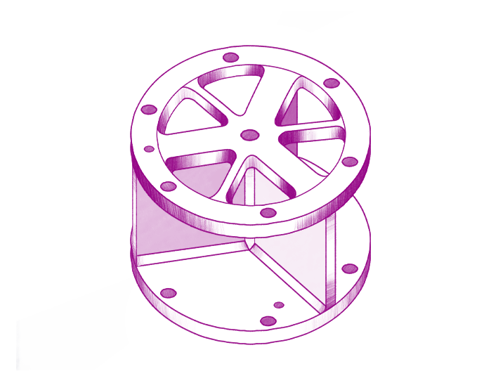
Removing debris from orbit is difficult. One needs to take into account many factors and one of them is that satellites are all different. For instance, ESA’s world-first Clearspace-1 mission is focusing on a relatively small and light object: a VESPA Payload Adapter. Yet, the chaser requires complex technologies that can take into account specifics of the VESPA’s shape, size and movement.
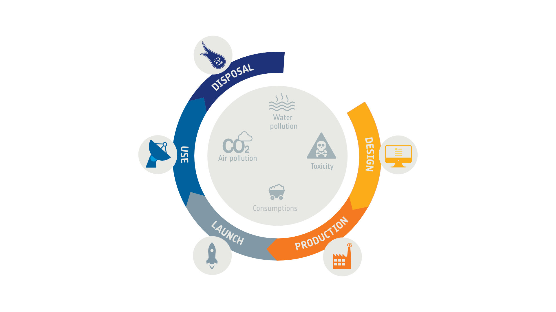
At ESA, our Clean Space activities look into the future and, inspired by what is done on Earth to reduce trash, we have started to design technologies to ease the removal of future satellites. Indeed, it is not possible to guarantee that a satellite won’t fail before its end-of-life manoeuvres (if operators follow good practice in space, the spacecraft will be deorbited to burn up, if in LEO, or sent below or above the GEO ring).
Two scenarios could apply to satellites as candidates for removal:
- Those that are still able to communicate with ground and, most importantly, that can control their attitude: there are cooperative.
- Those that have failed and for which there is no way to effect control: these are uncooperative.
The latter are much more challenging to remove. The first reason lies in the attitude of the uncooperative satellite. Depending on the type of failure, it may be tumbling at high rates around some random axis. Here, ‘high rates’ depends on the type of satellite, and especially on its mass, but in all cases the issue is the same: if the satellite is tumbling too fast, it is too risky to attempt a capture.
In this post, we are going to look at the most promising technologies for satellite removal. These technologies are currently under development at ESA.
Magnetorquers
A solution could be to embed passive capabilities that would allow the spacecraft’s tumbling rate to be dampened, once triggered. This point is important: the capability should allow nominal operation, but then turn on automatically as soon as a critical failure is detected.
For this reason, the Clean Space team have been investigating a technology to enable the ‘short-circuiting’ of magnetorquers at end of life.
When magnetorquers are short circuited, they form a closed electrical circuit. This closed circuit is surrounded by Earth’s magnetic field, and because of the satellite’s tumbling motion, the magnetic field in the satellite’s rotational frame is actually time varying.
From Faraday’s law of induction, eddy currents are therefore generated within the magnetorquer’s wires which, from Lenz’s law, implies the creation of an electromotive force opposing the motion.
In such a case, the motion is the satellite’s tumbling and the short-circuited magnetorquers would produce a torque that helps damp this tumbling rate. The rotational kinetic energy is dissipated through Joule effect inside the magnetorquer.
Short-circuited magnetorquers use the most basic laws of electromagnetism to brake an uncooperative satellite and make its capture by a chaser vehicle much more feasible.
Laser retroreflectors
Even if the magnetorquers are successfully triggered into action when the spacecraft fails, today there exists no direct way to know if they managed to damp the angular rate to an acceptable value for capture (since there is no contact with the satellite). Therefore, the spacecraft’s attitude must be tracked remotely from ground.
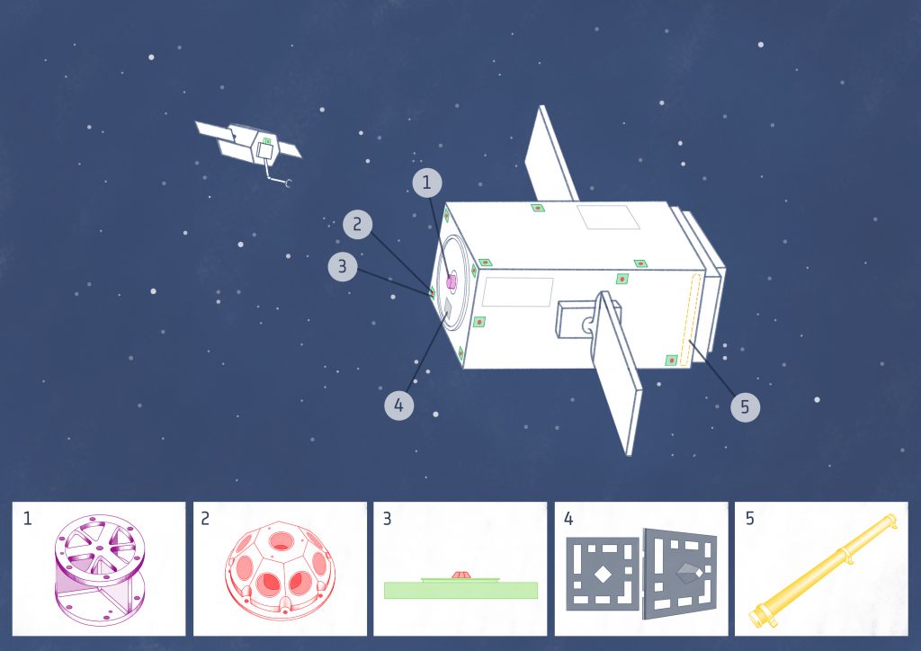
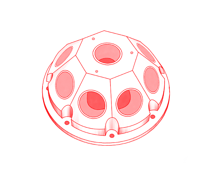
We are investigating a technology based on Laser Retro-Reflectors (LRR). Laser Retro-Reflectors consists of an array of cubes mounted on a hemispherical frame. They are designed to reflect light back in precisely the same direction it came from to provide independent measurements of the satellite’s position. According to past experience, it is possible to model the attitude of small tumbling satellites in LEO using several ‘corner cubes’ distributed on a satellite’s faces (Peiyuan Wanga, 2018). This physical positioning must be known in advance, and the positioning of the LRR should create different patterns on each face of the spacecraft.
Once the spacecraft is in orbit, a ground station transmits a laser beam, which reflects from the LRRs. The reflected signal includes information on the observed face such that, after interpretation, the spin rate and the spin axis of the target can be characterized.
If a failure occurs, a removal mission can be launched if the data given by the LRRs meets the tumbling requirements for capture. Then, the dead satellite would be a known, viable target for removal.
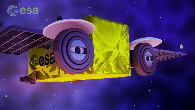
Markers
A chaser must be equipped with capture mechanisms to capture its target and effect deorbiting. However, before reaching the point where those mechanisms can come into play, the chaser must achieve a very near stand-off distance from its target. Only then can the capture phase can start. This approach, called rendezvous, is extremely complex.
As just one factor, rendezvous has to deal with illumination conditions, which can change very quickly and often in orbit. If a satellite is not prepared for rendezvous, then detecting it from a far distance is quite difficult, especially during an eclipse.
In such a context, we have been exploring several features to make the rendezvous phase achievable. One solution is to embed markers on the target that could support relative navigation between the chaser and the dead satellite.
This was one technique that enabled ESA’s former ATV vehicles to achieve automated rendezvous and docking with the ISS – a highly cooperative target!.
ATV navigation is based on cooperative rendezvous technology. At long range, relative GPS navigation is used, based on data from ATV’s and the International Space Station’s GPS receiver measurements. At short range, navigation uses optical sensors on ATV (videometers and telegoniometers) that bounce off a set of targets on the Space Station, the so called retro-reflectors.
The objective of these markers is to provide information on the range between the chaser and the target. They should also enable ‘pose estimation’ of the target, which allows its tumbling motion to be characterized. Finally, they will also provide a reference target for the chaser to aim at. Of course, getting this information requires specially adapted cameras on the chaser. The design of the markers must therefore always take into account the type of cameras that can be used in orbit.
There are two main types of cameras used in orbit:
- Visual cameras, which are high-resolution and often space-qualified, but rely a lot on illumination conditions.
- Infrared cameras, which are more robust to illumination conditions, but this technology is not as advanced for space operations as visual cameras, especially regarding resolution.
Taking into consideration the needs required of both visual and infrared, Clean Space has carried out studies on 2D and 3D markers.
- 2D markers
First, from 50 to 5 m relative distance, the chaser will make use of some small 2D markers located on the target’s surface. They will contrast with the satellite background both visually and thermally. Instead of having one big visual/thermal marker with a characteristic pattern to determine the target’s attitude, it was decided to ‘draw’ a pattern by locating multiple smaller markers on several faces of the spacecraft. The pattern of these on each face has to be unique so that it is possible to identify the face and therefore reconstruct the attitude of the target.
Further, the laser retroreflectors that also have to be scattered across the different target’s faces will be integrated to these 2D markers so that the patterns are the same for LRRs and markers.
However, when the chaser gets closer to the target, there is a point from which the chaser’s cameras won’t be able to observe the full target anymore because of field of view limitations. When this point is reached, relative navigation can’t rely on the 2D markers anymore. That is why the target should also embed a different type of marker.
- 3D marker
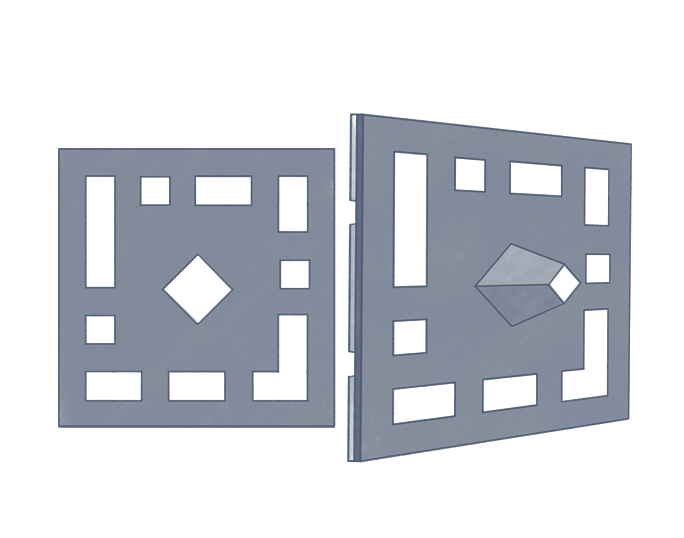
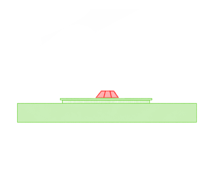
Only one 3D marker is needed, which has to be located on the target face to be captured by the chaser. Indeed, this marker would only be used for final approach leading to the capture.
The 3D marker requires an active illumination source on the chaser, in addition to a visual camera. The protrusion of the 3D marker, coupled with a painted pattern, gives different images depending on the relative position of the chaser.
Capture
Once the stand-off distance has become small enough, the capture can start. This is a critical phase of the mission, and it is even more challenging when the target satellite is unprepared for removal. Indeed, it is hard to determine a specific portion of the dead satellite that can be safely grabbed and that can sustain the capture loads. This is also extremely difficult because the chaser has to deal with appendages – like solar panels — that can restrict the potential capture areas.
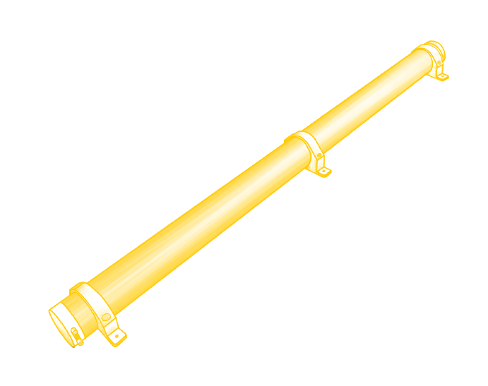
To assist in the capture phase, ESA has been carrying out a study to develop a mechanical interface. It is a single piece made of stainless steel about 10 cm wide and 5 cm high. It is designed to support the capture loads and also to enable a gripper (also to be developed) to grasp this interface. In that respect, a ‘keep-out’ zone must be enforced on the target side to allow this future gripper to operate.
Conclusion
To summarise, removing a satellite from orbit is very challenging. However, it is likely that such removal operations will become common in the future. In that context, providing technologies to ease the removal of a spacecraft while not putting too many constraints on its design is valuable for the space sector. This could pave the way for possible ‘Design for Removal’ standards in European spacecraft builders and therefore improve the sustainability of in-orbit activities.
References
Peiyuan Wanga, H. A. (2018). kHz SLR application on the attitude analysis of TechnoSat. 21st International Workshop on Laser Ranging. Canberra.
This post has been prepared by Paul Guintrand, system engineer intern at ESA in 2020-2021 and illustrated by Sacha Berna, scientific illustrator.

Discussion: 2 comments
Hi,
Intro: I am just an old bloke with an idea and not connected with the university.
I have a question – would it be possible for a small moon to be formed through the coagulation of planetesimals? (in this case “space junk”).
Thank you for your time and thoughts
David
The short answer is no. The perturbing forces are just too large. At the scale of space debris (rocket stages, big satellites, etc), the objects are pushed apart by even extremely weak forces, such as solar pressure. Gravity between the two objects is just far too weak, unless one of those objects is really large……like a moon