In this series of blog posts we will look at each operator of subsystems of the European Service Module for Orion, talking to the people that are on console during a mission who know the lunar spacecraft better than anybody.
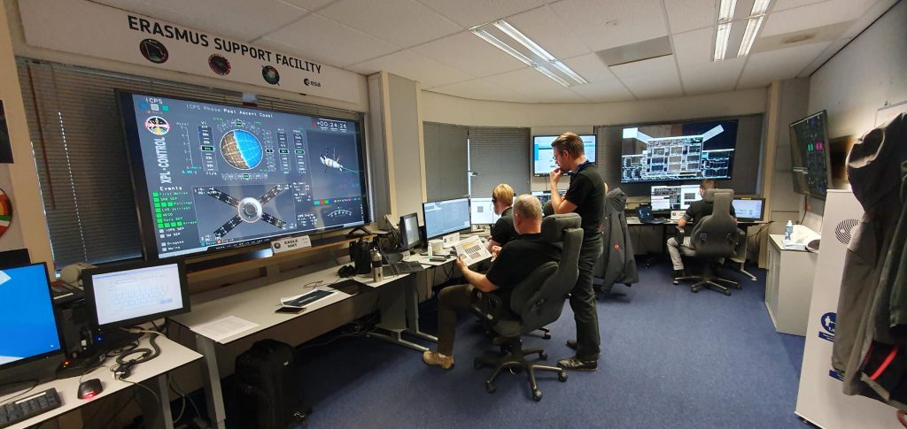
Mechanisms and POwer
This is two-in-one position, merging two specific competences.
The people who take care of Mechanisms and POwer (yes the abbreviation MPO is for Mechanisms and POwer) look at electrical power and the solar array wings.
“Finally the time has come for what I have been waiting for my entire life,” says ESA European Service Module system engineer Jens Laursen on the MPO team, “It has been a long journey since childhood with dedication, passion and determination to finally have this position monitoring the journey for multiple crews going back to the Moon and beyond!”
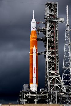
When Artemis is on the launchpad, the Mechanisms and Power personnel on console will be monitoring the state and health of their system and turn on equipment one by one. Before lift-off, power is provided from ground connections.
Heart of the subsystem
The Power Control and Distribution Units are the Mechanisms and Power most precious equipment, or as Airbus’ engineer Georges Lorjou puts it, “the PCDU is the heart of the power subsystem, distributing all electricity throughout the European Service Module to the Crew Module and the Crew Module Adapter.”
In the hot seat
The ascent phase is an important moment for the people on console. Georges explains: “Not only do many things happen in a short time, but it is the first time we see everything working together in flight, and it is challenging to have several critical operations happen at the same time.
”This is where we rely on the great team we have, and the days spent in simulations, in the end we all rely on each other and excellent teamwork.”
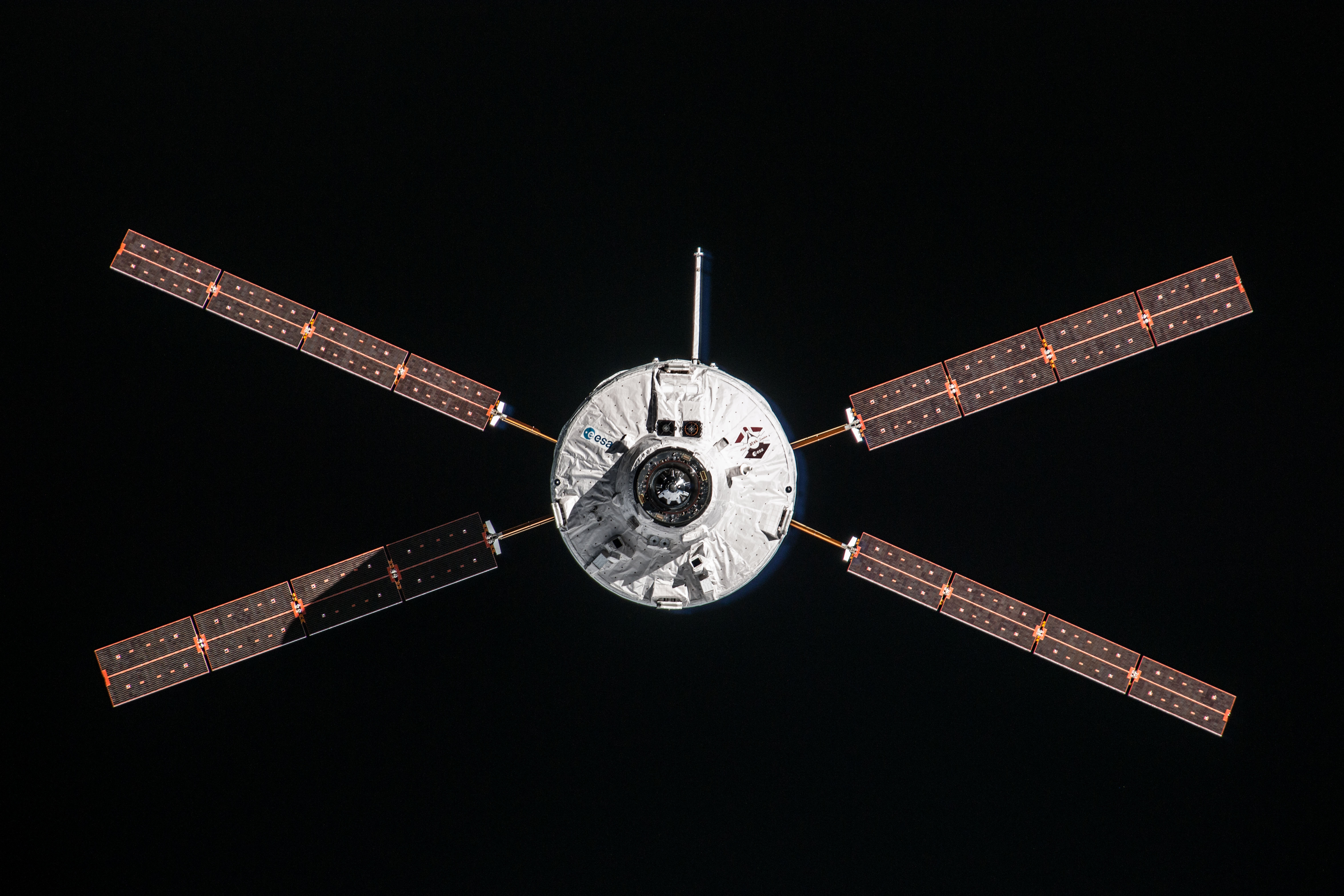
During lift-off Orion relies on batteries until the solar panels are deployed. This is a key moment, because without electricity not much is going to happen, and without the solar panels generating electricity the batteries will quickly deplete. The wings are deployed just after 18 min after lift-off and most of Artemis mission they are in sun-tracking mode to maximise the amount of generated power.
When the European Service Module fires its engines the solar wings are positioned safely to ensure they can withstand the loads generated from the thrust and to keep them safe from the hot engine exhaust plume, but also to avoid contaminating the solar cells from pollution that could cover the arrays and lower their efficiency. At the end of all the four wings, cameras offer a view of Orion – the whole spacecraft can be moved to capture beautiful photographs of the Earth and Moon in the background – a spacecraft-selfie with unique background.
Critical for the Mechanisms and POwer personnel is the deployment of the solar arrays. Once they are deployed and start generating power, the team knows that the European Service Module will be able to generate the energy which is needed to perform the rest of the mission. Power is key for everything, and if a failure does occur in any subsystem, the person on the power console will undoubtedly be consulted. Diagnostic tools can be to look for power spikes, voltage levels and current draws. And yes, the Power person on console can be asked to try switching an element off and on again.
Screens, so many screens
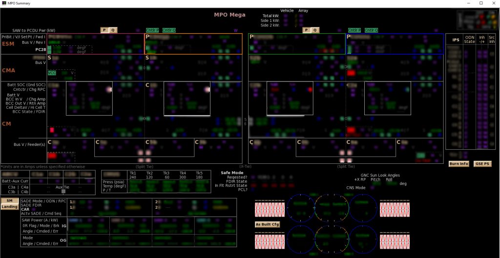
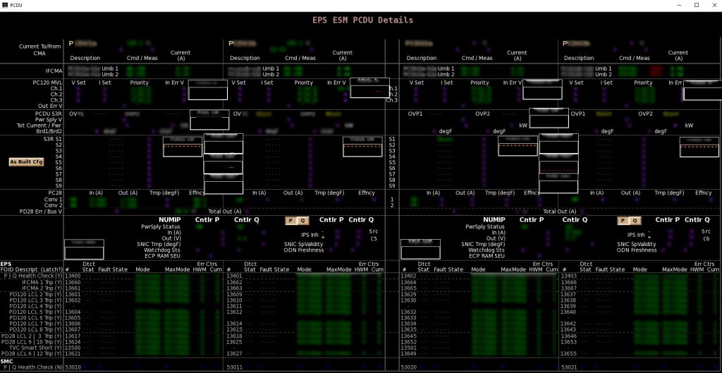
Let’s have a look at the screens that make up the MPO console. First up is the summary screen showing an overview of the voltage levels around the European Service Module. Four buses at 120 Volt provide power for the Orion spacecraft and they can be combined or even split for troubleshooting. The European Service Module has two of its own buses that operate at 28 Volt.
On the overview screen we also see information about each of the four solar wings orientation and how much energy it is producing.
Power distribution
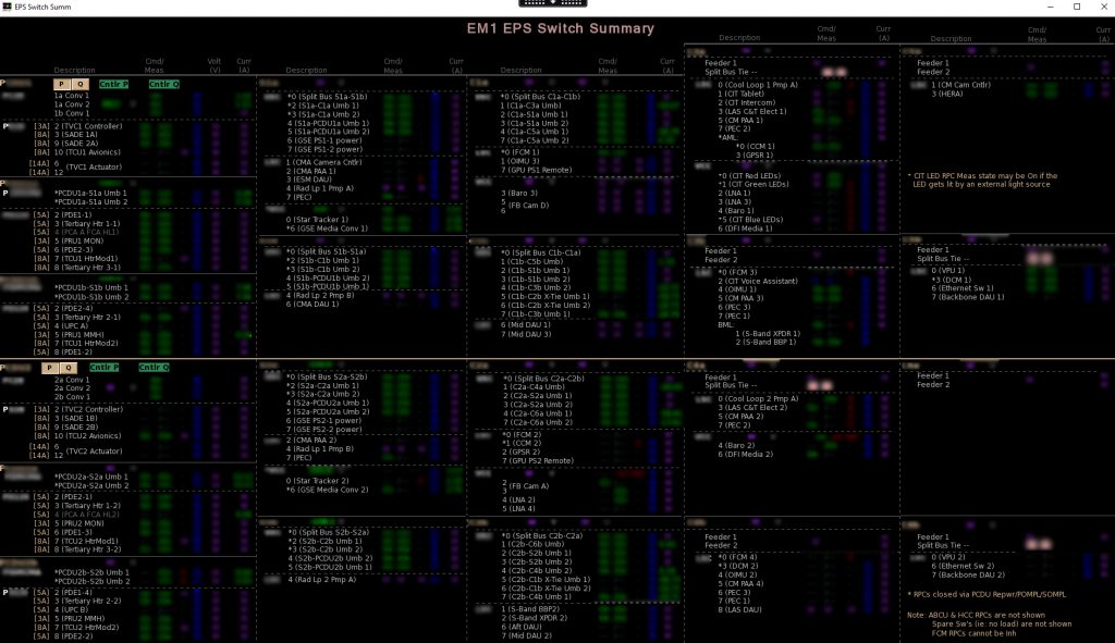
Power distribution is next, and this window shows all the switches for the European Service Module, each can be flipped from ground to be on or off. The screen also shows the basics of electricity: voltage and current levels to each subsystem. The software will flag and alert the operator if it detects any potential errors and can even decide on its own whether any electrical lines should be cut off. If the software detects a problem, it will switch off the faulty equipment automatically and raise a flag. Flight controllers can then execute applicable procedures (such as a reconfiguration), while the personnel in the Mission Evaluation Room will start investigating to understand the root cause and suggest troubleshooting steps as well as further steps if necessary, including the impact, if any, on the rest of the mission.
The screen is mostly abbreviations, and we will not go into each one, how many do you recognise? Some are listed in our handy ABC of ESM post.
Power in the details
The third screen shows the details on the Power Control and Distribution Units. Here we see the internal voltages of each module that work together to provide continuous power in case anyone would fail.
It shows details on the power going to the Crew Module and Crew Module Adapter, how the 120 Volt buses are behaving as well as the secondary 28 Volt European Service Module buses. The screen also shows details on power coming from the solar arrays and lastly temperature information on the PCDUs themselves. Just like a desktop computer, keeping the chips cool to prevent overheating is an important factor in keeping the system running smoothly.
Wing deployment
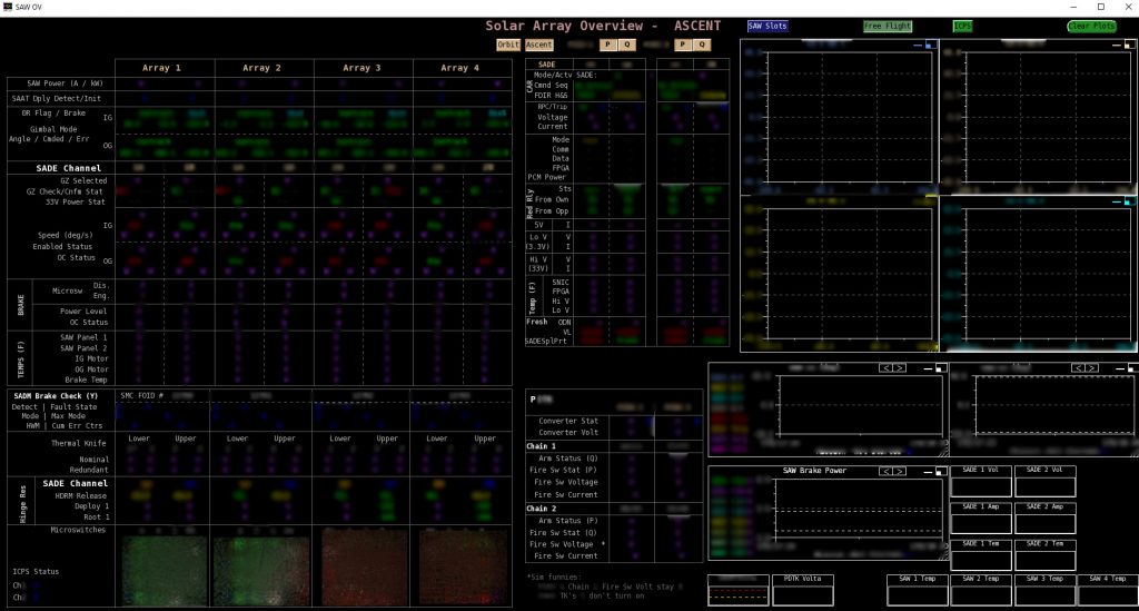
Lastly, let’s look at the solar array wings. This detailed screen is especially used during launch when the critical phase of deployment occurs. It has a setting to swap between various layouts. The ascent, or deployment screen, monitors the sensors for deployment but afterwards will change to display the engine burn plan so the MPO team prepare to monitor solar wing positions.
Another layout change for the graphical display that can be swapped during the Artemis mission is for the so-called green zones, these are pre-defined zones where the wings are allowed to move without risk that the panels would touch and damage Orion. Before the large Trans-Lunar Injection burn is performed by the second stage, a more limited green zone is in place to avoid touching the Interim Cryogenic Propulsion Stage. During the second stage burn, the solar array wings are positioned to withstand the loads and to avoid the exhaust plumes with brakes engaged to block the solar wings in position. After separation from the second stage the next green zone has more freedom for wing movement and can be selected on the screen to monitor their sun-tracking mode and ensure they are generating as much as power as possible during the flight.
Other important data to survey on this screen are the position of the wings, speed and direction of all eight mechanism axes (two axes per wing) simultaneously, temperatures of the mechanism and wings, general electrical health of the system, the mechanism brake and the status of hardware backups.
Jens concludes “all these numbers and data sometimes makes us forget that we are monitoring and helping fly the coolest X-Wing spacecraft around and that we will be taking beautiful photographs with it too – it’s an amazing job to have and we are all committed to go forward to the Moon!
“As a kid, like many I loved Star Wars, and now we are in position to deploy the x-wing (solar wing) configuration, and it makes me smile every time I think of it”.
 Automated Transfer Vehicle page
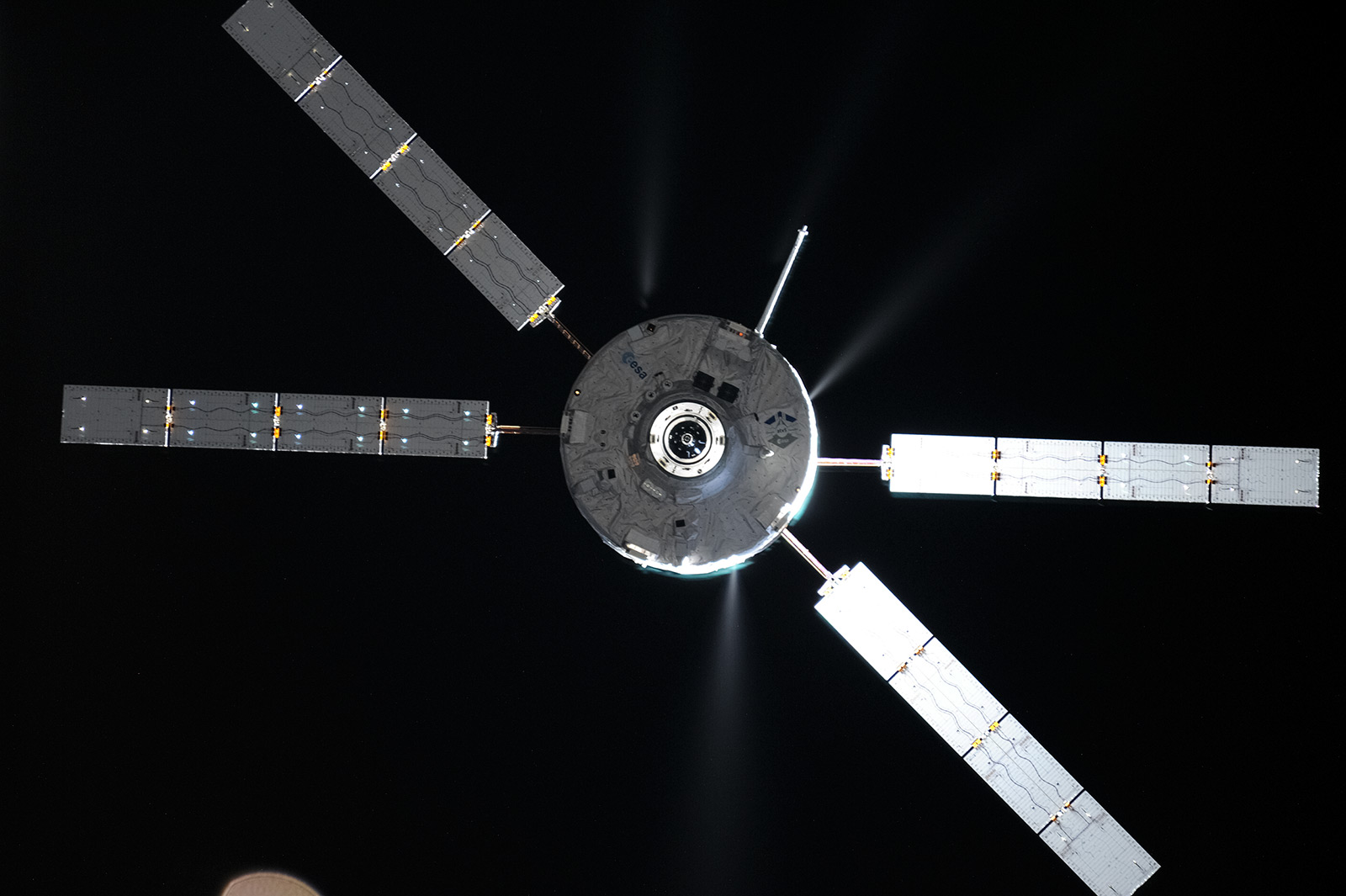 ATV blog archive
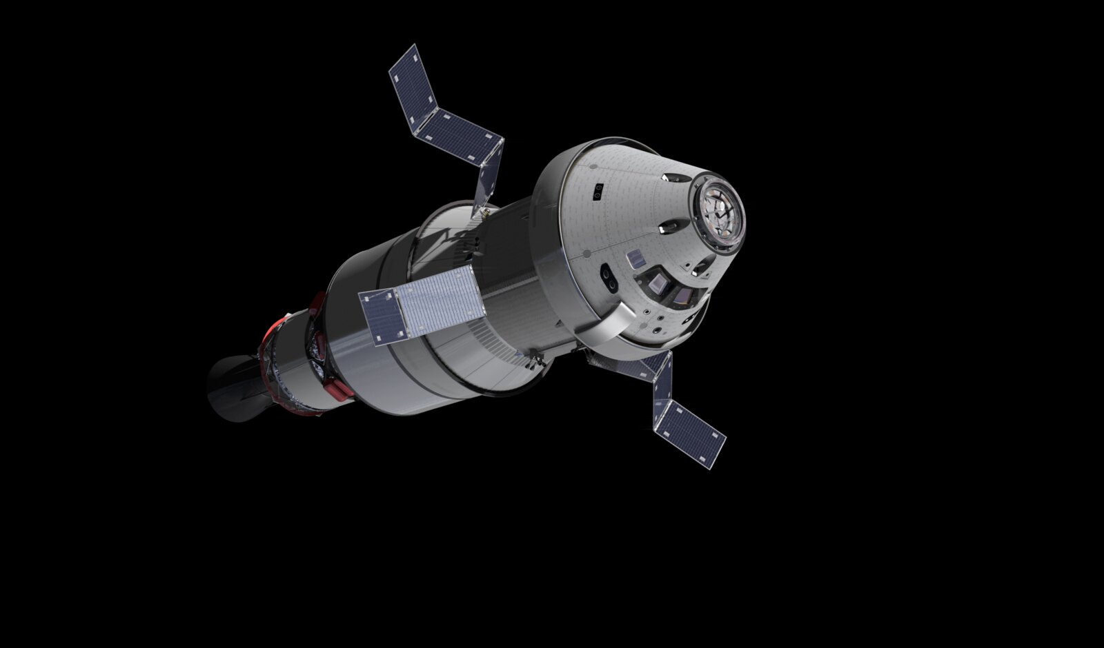
 NASA Orion page
 Airbus Orion page
Discussion: one comment
It’s really touching and “hyggeligt”(Jens might understand this word) that even at Jens’s level, one is driven by a childhood dream! The linguistic hint makes me think of what ESA will be able to bring to space programs: a somehow not completely uniform approach for problemsolving, because of a collaboration of so many countries!
Thanks for the dream!