Editor’s note: Here’s the next installment in the continuing story of how the Mars Express team is preparing for Comet Siding Spring flyby, 19 October 2014. This week: introducing the spacecraft’s subsystems and structure – and wondering how we can absorb impacts.
Now that we have looked at some of the external factors affecting Mars Express, let’s take a look inside and see how the spacecraft was built and what it’s made from.
This diagram shows the major components in the spacecraft body. There are a lot of acronyms, which we will explain in more detail in future postings. For now, briefly:
- AOCS (blue): Attitude and Orbit Control System – this controls where Mars Express is pointing (the attitude) and can change the speed of the spacecraft to modify its orbit.
- DMS (pink): Data Management System (sometimes also called OBDH – On-Board Data Handling) – The computers and storage that interpret commands from Earth, collect data from sensors and transmit telemetry back to Earth.
- Instruments (purple): The payload. The sole purpose of Mars Express is to carry provide support to these by pointing them at their targets, collecting their data, keeping them at the correct temperature and feeding them with power.
- Power/Thermal (green): Generating, storing and distributing electricity throughout the spacecraft and maintaining the temperature within acceptable limits.
- TT&C (yellow): Tracking, Telemetry and Control – the radio communications system of Mars Express.
There is one other subsystem that we will look at in a little more depth today – Structure.
This ‘system’ is the only subsystem that we cannot change in flight – but with the upcoming comet encounter, and the possibility of any sort of comet dust impact, we have been looking at the structural design in much detail!
Each wall of the square, box-like Mars Express is made from aluminium sandwich panel. This comprises two sheets of thin aluminium separated by a honeycomb of aluminium.
These panels are very popular in many aerospace and motorsport applications as they have fantastic strength-to-weight ratios and are incredibly stiff, which is extremely important when factors like the alignment of instruments is concerned. The trade-off in this case is that we are using thin materials with thicknesses similar to that of a carbonated drink can, which – while very strong – does not provide much protection from hypervelocity impact penetration.
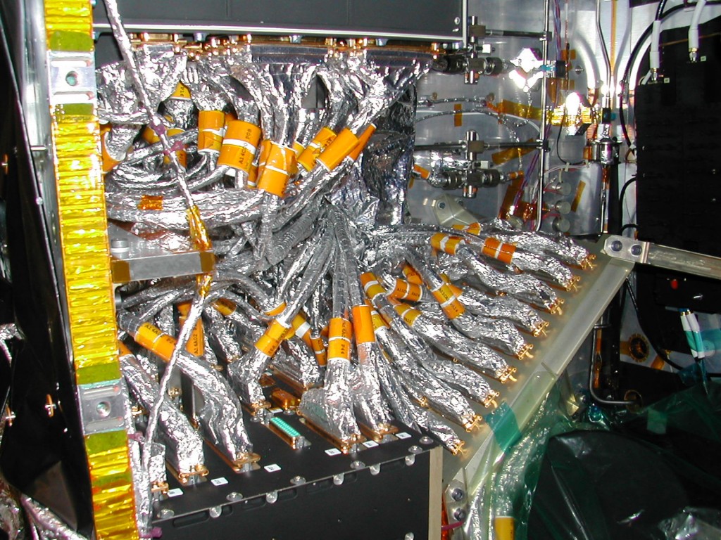
This picture is of the right wall, looking in from the front. The aluminium sandwich panel is visible on the left of the photo and is 20mm thick.
The three black boxes are the CDMU2 (bottom), RTU (top) and the RFDU (right). A reaction wheel is also visible, at bottom right.
The other thing you probably noticed is the harness – the huge mass of cables that connect the different parts of the subsystems together.
The solar arrays are of the same construction and the high-gain antenna is based on an aluminium core but is has an additional skin on either side with six layers of carbon-fibre composite.
Now, we’re sure that some of you are thinking that this is mad – how could we possibly send such a valuable spacecraft out with so little protection? Well, the first answer comes from the Hitchhiker’s Guide to the Galaxy:
“Space is big. Really big. You just won’t believe how vastly, hugely, mindbogglingly big it is. I mean, you may think it’s a long way down the road to the chemist’s, but that’s just peanuts to space…”
In normal circumstances, the chances of our spacecraft being hit by anything significant is quite small. For a spacecraft, the worst place to be (with the exception of a comet coma) is in low-Earth orbit, and even in this relatively cluttered environment, only a few spacecraft have ever suffered enough damage due to impacts to have their missions affected.
Unfortunately, while the chances of an impact are normally very, very low, should an impact happen, it can be quite devastating. Why? Here’s the other thing to remember: in space, collisions tend to be fast – very fast – and the energy of a collision increases with the square of the speed.
At such energies, impacting particles/objects and any part of a satellite they hit behave more like liquids than solids, and break up violently. Spacecraft that have been designed to operate in environments where they need to be protected from impacts use a system called a Whipple shield for protection – serving basically as armour plating (see “Hypervelocity impacts and protecting spacecraft” for much more detail – Ed.).
In Whipple shielding, a thin plate is mounted some distance offset from one or more additional shield plates. The first one will cause any impacting object to break up into fragments, and then the multiple layers behind this absorb the remaining energy of the fragments.
One of the best examples of this was ESA’s Giotto probe that flew just 596km from Halley’s comet in 1986.
Mars Express was not built with a Whipple shield and as it was not expected to face such a fierce environment as Giotto, but we’re sure you can work out from the image at the top of this post (and from last week’s post on pointing restrictions) which side is the least vulnerable (we think it’s the front of MEX – with the big radio antenna acting as a Whipple shield! – Ed.).
Of course every decision we make is a trade-off, and we will see why in later weeks.
– Andy, Michel, Kees, Simon and Luke


Discussion: no comments